Artificial Magnetic Conductor (AMC)

Introduction
Artificial Magnetic Conductor (AMC) structures [1, 2] also known as High Impedance Surface (HIS). One of most interesting application of AMC is in the design of efficient and low-profile antennas [3–7]. Currently known AMCs are inherently frequency-selective and suffer from narrow band property which limits their applications in wideband or multiband antenna applications. The particular area of interest in this study is the investigation into the possibility of employing automatic optimization of elementary AMC cell geometry to tune its frequency characteristics i. e. its center frequency and bandwidth.
- Methods
Artificial Magnetic Conductor (AMC) is a type of metamaterial characterized by negative magnetic permeability. What isunique in AMC metamaterial that phase reflection angle near to zero. Unlike normal electric conductors, the phase of the electromagnetic wave reflected on this artificial magnetic conductor is phase-shifted by an angle β of between −90° and +90° relative to the incident electromagnetic wave (in some other applications this range is limited to -45° and 45°) – see fig 1. Of Course, this phenomenon only occurs for specific frequencies. The main goal of this research is learn how we can control these frequencies.
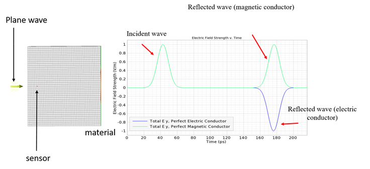
Fig 1: Reflected wave characteristics: from normal, electric conductor and magnetic conductor.
Fig 2 presented general characteristics of µ-negative surfaces. In both cases most important part is network of resonators (usually Split Ring Resonators (SRR) as resonator is used). Because a SRR may be described as a RLC circuit then SRR network also may be treated as network of coupled RLC circuits. Finally, metasurfaces couble be modeled into two ways: using full elecktromagnetic simalations and circuit-based model.
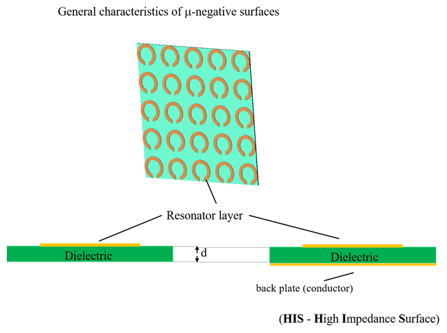
Fig 2: General characteristics of µ-negative surfaces.
It should be observed that geometrical parameters of SRR are strong determine the electric properties of RLC circuit, particularly: radius and path width of SRR are determining of inductance of resonator (Lin), moreover gap with and path width are determining of gap capacity (Cg). From R, L and C parameters depend characteristics of resonator, especially resonant frequency and q-factor (quality factor). in the case of resonators network, mutual (magnetic and electric) couplings they are also important. From the point of view of physical phenomena mutual coupling of two resonators results from the distribution of flux’s - electric and - most of all - magnetic. Mutual inductance between the resonators also could be calculated using the methodology proposed in [4].
The goal of the optimization was to improve the AMC structure in terms of two objective function components: the bandwidth and the center frequency. This may be done into two ways: by geometry optimalisation with full field model or circuit-based model.
In first case given model AMC were evaluated from the numerical simulations performed using the Remcom XFdtd. The AMC geometry model was created automatically in each iteration of the optimization loop using the geometry parameter values for each new offspring of the evolutionary algorithm (ESTRa) [5].
In second way the currents distribution on each SRR were evaluated from the circuit-based model of network of coupled resonators. The key is: resonant frequency is correspond to 0° reflection phase and also band is depend on q-factor (the lower the q-factor value, the wider the bandwidth). A low-computational-cost lumped-element (or distributed-element) equivalent-circuit models could be using with PSO (Particle Swarm Optimization) algorithm. Thanks to low-computational-cost of model a huge number calling of objective function is possible in reasonable time.
- Results
- The main goal of the current study is to learn to what extent it is possible to improve the performance of a particular AMC based of given n-parameter geometry of an elementary cell.
- The second aim is to investigate whether it is possible to achieve this by employing an optimization approach.
- Third goal is checking which model: field, circuit or mixed is optimal to solve of this problem.
- Conclusions
- Contact
- Dr. Łukasz Jopek
 , e-mail: This email address is being protected from spambots. You need JavaScript enabled to view it.
- Dr. Łukasz Jopek
- Publication
- [1] D. Sievenpiper, L. Zhang, R. F. J. Broas, N. G. Alexopolous, and E. Yablonovitch, “High-impedance electromagnetic surfaces with a forbiddenfrequency band, ” IEEE Trans. Microw. Theory Tech. , vol. 47, pp. 2059–2074, Nov. 1999.
- [2] Sievenpiper DF. High-impedance electromagnetic surfaces. PhDdissertation, University of California, Los Angeles; 1999
- [3] Zhang Y, Wang BZ, Shao W, Yu W, Mittra R. Artificial ground planes for performance enhancement of microstrip antennas. J Electromagn Waves Appl. 2011;25:597–606.
- [4] Abu M, Rahim MKA, Ayop O, Zubir F. Triple-band printed dipole antenna with single-band AMC-HIS. Prog ElectromagnRes B. 2010;20:225–244.
- [5] Di Barba, P.; Mognaschi, M.E.; Lowther, D.A.; Sykulski, J.K. A benchmark TEAM problem for multi-objective Pareto optimization of electromagnetic devices. IEEE Trans. Magn. 2018, 54.